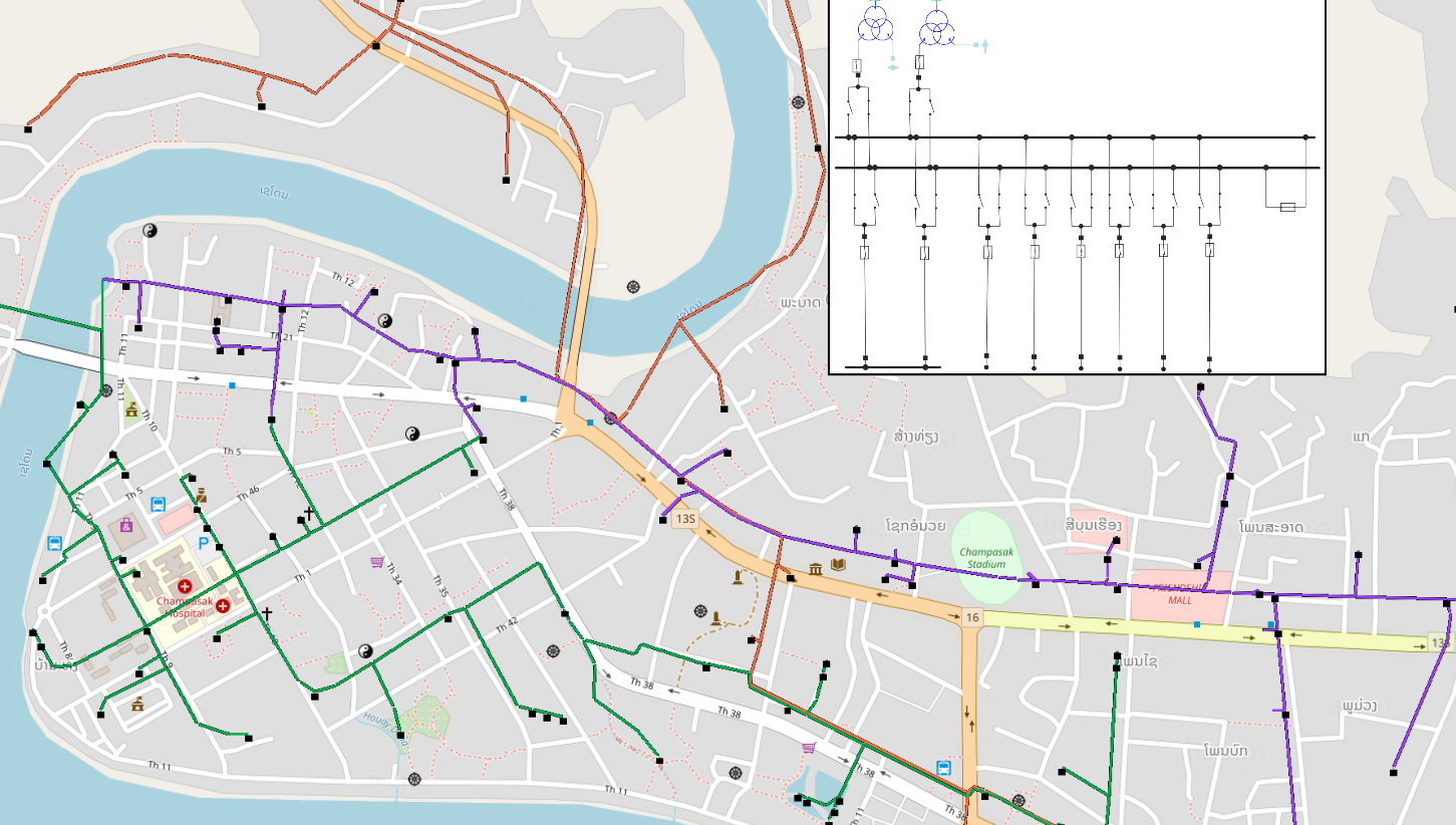

For example, a model which is used for control purposes can be different to the ones used for circuit design or load flow calculation. They can be obtained from the system knowledge or from experiment tests.Īccording to how the model is interpreted and for which purpose it will be dedicated, the representation of a model may be different from one to another goal. Depending on the control law type, these models can be linear or nonlinear time domain or frequency domain, continuous or discrete. Controlling: The control design needs specific models.Moreover, it allows engineers to reach a given objective by choosing an adapted set of decision variables.

In the same aim as above, the use of model allows the determination of the constraints applied to the component.
#DFIG IN NEPLAN HOW TO#
In addition, we describe how to implement components such as a variable resistor that is not provided in the Simulink's library. The equivalent model of both wind power generation system and MMC are presented in this paper. Hence, in this paper, we propose a real-time implementation model employing a detailed equivalent model (DEM) using MATLAB/Simulink. Although some studies have introduced the HILS model of MMCs for grid connection using PSCAD/EMTDC, it is difficult to find a study in the literature on the model using Matlab/Simulink, which is widely used for power electronic simulation. A real-time operation model of the MMC is required to conduct a HILS experiment.
#DFIG IN NEPLAN SOFTWARE#
The application of the MMC is a system that connects wind power to a grid through high-voltage direct current (HVDC) in the form of back-to-back connected MMCs, whereas a HILS is a system used to test or develop hardware or a software algorithm with real time. In this study, we propose a wind power generation system model for operating modular multilevel converter (MMC) in a hardware-in-the-loop simulation (HILS) application. Although some studies have introduced the HILS model of MMCs for grid connection using PSCAD/EMTDC, it is difficult to find a study in the literature on the model using Matlab/Simulink, which is widely used for power electronic simulation

MATLABSolutions demonstrate how to Implementation of The application of the MMC is a system that connects wind power to a grid through high-voltage direct current (HVDC) in the form of back-to-back connected MMCs, whereas a HILS is a system used to test or develop hardware or a software algorithm with real time.Ī real-time operation model of the MMC is required to conduct a HILS experiment. Simulation of dfig based wind turbine using mmc converter in MATLAB


 0 kommentar(er)
